Estonian oil shale
Compiled by Mihkel Koel in 1999
1. Resources
There are two types of oil shales in Baltic Basin: the Middle Ordovician kukersite mined in the Estonia and St.Petersburg fields (Russia), and lower Ordovician Dictyonema shale. The Dictyonema shale occurs on an area of about 11000 km2 in the northern and north-western parts of the republic at a depth of 10-90 m; the thickness of the seam is 1-8 m. Reserves of this shale considerably surpass those of kukersite. At same time, the quality of the shale is poor: heating value 5-8 MJ/kg, oil yield (Fischer Assay) 3-5 %, sulfur content 2-4 %. This prevents their utilization for energy production and processing into oil [1].
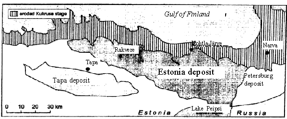
Fig. 1. Location of oil shale deposits in North-East of Estonia
The kukersite shale is the most important mineral resource of Estonia. There are two principal deposits in the republic: the Estonian located in the northeastern part of the republic. The productive seam thickness diminishes from 2.7-3.0 m in the northern part of deposit to 1.4-2.0 m in the southern and western parts; the Tapa deposit is situated southwest of the Estonian deposit with seam depth below the surface 60-170 m. The seam has maximum thickness 2.0-2.3 m in the central part of the deposit. This deposit is not in use at the moment. These two main deposits cover an area of about 5 000 km2.

Fig. 2. Stratigrafical position of kukersite deposit
The Estonian deposits were first developed in 1920-s after the state achieved independence. In 1939, about 1.7 Mtons were proceeded. About 60 % of the shale was retorted to obtain fuel oil; the rest was burned directly for process heat and power generation. From the 1950’s the main use was changed to power generation by burning in power stations. Oil shale became the main energy source for Estonia and North-West part of Soviet Union, and its use in power stations and for processing of oil rise rapidly.
Oil shale mining production reached its maximum level of 31.35 Mtons per year in 1980. Because of changing economical situation after liberation in 1990, the need for energy production decreased and former markets for shale oil disappeared, oil shale mining decreased and minimum level of oil shale mining was 13.5 Mtons per year (in 1994).
It is taken the energy rating of 35 GJ/m2 (about 10 MWh/m2) as a critical value for mineable bed to estimate existing resources. Estonian mining fields have the energy rating from 36.5 to 46.3 GJ/m2, with an average of 42.2 GJ/m2. Taking account about 20 % higher than minimum limit, Estonian oil shale mine fields have approximately 109 tonnes of mineable reserves and exploration fields have double these reserves [2].
On January 1, 1997, the oil shale reserves accounted in the balance of mineral reserves of Estonia were the following [3] :
¤ Active proved reserves – 2.23 × 10⁹ tonnes
¤ Passive proved reserves – 0.78 × 10⁹ tonnes
¤ Active probable reserves – 1.68 × 10⁹ tonnes
¤ Passive probable reserves – 1.25 × 10⁹ tonnes
The regulation concerning the geological exploration of mineral resources and establishment of mineral reserves provided the following [4]:
Oil shale shall be regarded as mineral resource if:
¤ the calorific value of the bed is not below 6.1 MJ/kg (1450 kcal/kg)
¤ bed thickness is not less than 0.5 m at the overburden thickness of up to 10 m
¤ or bed thickness is not less than 1.4 m at the overburden thickness of over 10 m.
2. Mining
Either underground or opencast methods are used to mine oil shale. The big part of Estonian geological oil shale resources are found in deeper layers than economically justified for opencasts, i.e. deeper than 30 meters. The largest mine is Estonia mine with mining in 40-70 m deep. Other five are smaller and lower.
There are three opencasts Sirgala, Aidu and Narva, and they give oil shale with cost price 63.5-70 % of the cost of mine [5].
Average calorific value of mined shale:
Estonia - 9.0 GJ/t; Sirgala - 8.7 GJ/t; Narva - 8.3 GJ/t.
Oil shale is being enriched in five out of six mines. Settlers, slurry separators, air classifiers, flotators, and selective comminution equipment are used for this purpose. In this process 20 % of the mined energy is lost as unusable for generation. Only the relatively small Kohtla mine produces unenriched oil shale (0.6-0.7 Mt/year).
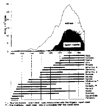
Fig. 3. Kukersite production over the years.
Horizontal bars indicate years of activityof mines and opencasts.
Annual output of Estonian oil shale mines [6]:
Mine |
Potential output, Mton |
Sompa |
0.60 – 1.20 |
Viru |
1.30 – 1.86 |
Tammiku |
0.90 – 1.35 |
Ahtme |
1.20 – 2.00 |
Kohtla |
0.75 – 1.10 |
Estonia |
3.40 – 5.40 |
Sirgala (open) |
2.50 – 3.60 |
Narva (open) |
1.80 – 2.50 |
Aidu (open) |
2.40 – 3.10 |
In 1997 year 6 mines and 3 opencasts mined in total 22 Mtons of oil shale. After partial enrichment 14.4 Mtons of oil shale was sold to make electricity (2 power plants), shale oil and gas (3 processing plants), and heat.
Oil shale mining imparts a variety of impacts on the environment. A new artificial structure of rocks with a new relief is formed (height up to 10-18 m and slopes up to 40 degrees) is formed during surface mining. About 115 km2 of territory is formed in such way [7]. About 85 % of mined areas have been reclaimed and form a permanent and real basis for postmining landscape. For example, 212 hectares of land was damaged during surface mining in 1996, 273 hectares was recultivated. 1450 ha or 13.9 % of damaged land has not bee recultivated yet [8].
Underground mining produces a big variety of new forms in landscape. The main features of this relief are the depressions – troughs and surrounding rising grounds. The total area of deformed but stable undermined ground surface is about 130 km2, not deformed but unstable area is about 100 km2. One of oil shale mining by-products is limestone waste. To prepare a trade product of oil shale, the separation of limestone from mined rock in special mills is necessary. As a result there are 32 waste piles near oil shale separation mills, which consist mainly 82-94 % limestone and 6-18 % residual oil shale 7. These piles have the form of truncated cones or plateaus up to 55m high and with diameter 130-360 m. Total area of those pile equals about 3,5 km2.
3. Main customers
There are three important customers of oil shale:
¤ Electric power company Eesti Energia 81 % of mass, 77 % of heating value
¤ Oil processing company Kiviter 16 % of mass, 21 % of heating value
¤ Cement factory Kunda Nordic Cement 2.4 % of mass, 2.3 % of heating value
Use of oil shale in latest years [9]:
|
1996 |
1997 |
1998 (estim.) |
Total sold (Ktons) |
15246 |
14456 |
14000 |
Power Stations |
12407 |
11700 |
11200 |
Chemical Industry |
2372 |
2362 |
2500 |
Other |
467 |
394 |
300 |
At the moment government price policies subsides oil shale processing at the expense of electricity.
Efficiency of the oil shale energy conversion against the mined oil shale can be taken about 37 %. Power plants are using the obsolete pulverized combustion boilers with efficiency 29 % (from mass of shale mined). It means big amount of ash and small particles after burning of this kind of fuel, but Estonian oil shale is rather specific fossil fuel because after the dissociation of carbonates (Ca and Mg) during combustion process, essential desulfurization of flue gases by ash sulfation in furnace and gas ducts takes place. The rate of sulfur capture is in range 40-90 % under different conditions [10].
Consumption of oil shale bed energy 2:
Electricity |
11.48 % |
Shale oil |
9.30 % |
Cement industry |
1.95 % |
Mining losses |
25.0 % |
Processing losses |
6.20 % |
Generation losses |
40.29 % |
Distribution losses |
5.70 % |
It is important to combine together technologies, which are able to use unenriched oil shale (calorific values down to 6.7 GJ/t), decrease the losses on electricity generation with new methods of burning (like circulating fluidized bed burning) and locally operated transportation.
3. Oil shale
composition
Oil shales are classified as “composites” which are tightly bound organics and inorganics. The organic matter of oil shale is composed mostly of kerogen with few percent of bitumen, the two being differentiated by solubility in organic solvents.
The main characteristics for kukersite (w/w %) [11]:
67 % |
|
organic matrix (kerogen) |
30 % |
bitumen |
3 % |
Elemental composition of kerogen (%):
C |
76.0-77.5 |
H |
9.4-9.9 |
S |
1.2-2.0 |
N |
0.2-0.5 |
O |
9.0-11.0 |
Cl |
0.5-0.9 |
H/C |
1.48 |
The organic matter of kukersite is considered to be entirely of marine origin, and consists almost entirely of accumulations of discrete bodies, telalginite derived from a colonial microorganism termed Gloeocapsomorpha prisca. As compared with other rocks containing telalginite, kukersite have low H/C (1.48) and high O/C (0.14) ratios and generally plots as Type II kerogens on van Krevelen diagram [12]. Major components of this kerogen are phenolic moieties with linear alkyl side-chains. In spite of the predominance of phenolic moieties kukersite appears as a highly aliphatic type II/I kerogen due to the presence of associated long, linear alkyl chains [13]. The formation of kukersite kerogen, as well as other G.prisca-derived kerogens, obviously occurred via the “selective preser-vation” pathway. The phenolic moieties of kukersite correspond to important basic structures of the resistant macromolecular material building up the selectively preserved thick outer walls of G.prisca colonies [14].
The G.prisca colonies have some resemblance to Botryococcus braunii colonies, adapted to salinity variations and exhibiting a high polymorphism and modifications in cell wall composition (especially in the level of phenolic moieties) controlled by salinity. Kukersite from Estonian deposit is practically the only Ordovician oil shale which on thermal processing yields oil characterized by a high content of oxygen, mainly phenolic compounds. These oxygen-containing compounds are thermally unstable and form carbonaceous residue in semicoke at higher temperatures.
Different extraction methods give bitumen yield from kukersite on the level of 1-3 wt.%.
A pragmatic index of oil shale value is the Fisher Assay, a standardized laboratory pyrolysis, which measures the oil obtainable from given weight under controlled conditions [15].
Fisher Assay values for some oil shales [16]:
|
Moisture content, wt.% |
Water |
Oil |
Residue |
Gas + |
Kvarntrop (Sweden) |
2.0 |
|
5.7 |
87.2 |
5.1 |
Kukersite (Estonia) |
Dry |
1.9 |
22.0 |
70.5 |
5.6 |
Green River (USA) |
Dry |
1.4 |
10.4 |
85.7 |
2.5 |
Irati (Brazil) |
4.6 |
1.2 |
6.9 |
83.6 |
3.7 |
Maoming (China) |
5.0 |
3.2 |
7.3 |
80.6 |
3.9 |
El Lajjun (Jordan) |
4.0 |
1.4 |
10.1 |
80.8 |
3.7 |
The inorganic portion of kukersite comprises a complex mineral suite which in main is carbonate (41 %), but contains also sandy-clay part (26 %).
Major mineral phases of kukersite are [17]:
Calcite |
CaCO3 |
|
Dolomite |
CaMg(CO3)2 |
12.6 % |
Quartz |
SiO2 |
11.8 % |
Pyrite |
FeS2 |
3.4 % |
Feldspar |
K2O × Al2O3 × 6SiO2 |
4.0 % |
Illite |
K2O × 3Al2O3 × 6SiO2 × 2H2O |
10.0 % |
Average composition of mineral parts (%) 11:
Sandy-clay part |
Carbonate part |
||
SiO2 |
59.8 |
CaO |
48.1 |
CaO |
0.7 |
MgO |
6.6 |
Al2O3 |
16.1 |
FeO |
0.2 |
Fe2O3 |
2.8 |
CO2 |
45.1 |
TiO2 |
0.7 |
|
|
MgO |
0.4 |
|
|
Na2O |
0.8 |
|
|
K2O |
6.3 |
|
|
FeS2 |
9.3 |
|
|
SO3 |
0.5 |
|
|
H2O |
2.6 |
|
|
Elemental abundance’s in the raw shales are correlated with mineralogy of the materials and are traceable to differences in the depositional environment of the sediments. Examination of major elements indicates less aluminum, magnesium, and sodium in the Estonian shale than in the Green River shale and comparable amounts of calcium and iron. These results are consistent with differences in the mineralogy. The Estonian shale contains no detectable amounts of alkaline earths, barium and strontium. The Estonian shale has less arsenic, cobalt, rare earth elements, uranium, vanadium, and zinc. The only elements with increased abundance’s, compared to Green River shale, are halogens, chlorine and bromine, indicating the marine nature of the depositional environment [18].
4. Retorting
Retorting is the process of heating shale to the temperature at which kerogen is decomposed or pyrolysed in the absence of oxygen into gas, condensable oil, and a solid residue. The inorganic mineral matrix of the shale is retained in the form of spent shale. Oil shale decomposition begins at relatively low temperature (300 °C), but proceeds more rapidly and more completely at higher temperature. The rate of kerogen decomposition is the highest at retort temperature of 480–520 °C on which the kerogen converts into three organic fractions: oil, gas and residual carbon. The following trends were observed: the oil yield decreased and the retort gas increased with increasing retorting temperature, the oil became more aromatic as temperature increased. Once gas generation ceases, unburned carbonaceous residue remains that sticks to the solid inorganic material of the original oil shale. The gases and vapors leaving the retort are cooled to condense the oils and reaction water.
Contrary to other oil shales, to obtain high oil yields from kukersite needs specific conditions of processing. It can be explained by the fact that on thermal processing of kukersite, its elevated moisture percentage and the predominance of calcium carbonate in its mineral part result in high values of specific heat consumption in the process 23. Also shale is rich in organic matter and must pass the temperatures of thermobitumen formation and coking at a relatively high speed to avoid caking and secondary pyrolysis of oil.
Retorting processes are generally of two types: those in which gas is used to transfer heat, and those in which circulated solids are used as heat carrier. The both type large-scale retorts are used in Estonia.
The Kiviter vertical gas generator (GGS) which is similar to the gas combustion on Paraho directly heated retorts. It was designed for the feed shale ranges from 25-100 mm. The retort is a vertical system internally heated by combustion of coke residue and non-condensable shale gas.
Operation of the Kiviter retort is continuos. Raw shale enters from the top and is heated to temperatures required to decompose the organic mater. Heat is provided by the rising gases supplemented by recycle gas burned in the heat carrier preparation chamber. The combustion products pass sideward through the descending shale and carry the oil vapors and evolving gas with them into the collection chamber. From there they are delivered to the condensing system. Additional recycle gas and air are admitted to the chambers near 900 °C point and heat the shale residue to burn off the coke. Recycle gas entering the bottom of the retort cools the spent shale, which then leaves the retort through a water-sealed discharge system [19].
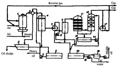
Fig. 4. Schematics of condensation system of retort GG-5. 1- retort,
2- decanting vessel, 3- gas collector, 4- primary washer, 5, 8, 14, 15, 18- pumps, 6, 16-
receivers, 7- oil separator, 9- drip pan, 10, 12- settling tanks, 11- water cooler, 13-
final washer, 17- gas blower.
During the entire post-war period the vertical retorts underwent a long process of development. In the early reconstruction’s the concept of central inlet of the heat carrier was used later replaced by a new concept of heat carrier gas cross flow in the retort (the Kiviter process). The significant increase in retort throughput rate was accompanied by increase in the shale oil yield from 65-70 % to 75-80 % of the Fischer Assay oil. A prototype 1000 ton-per-day Kiviter retort was developed and similar retorts started operation at “Kiviter” in 1980’s. Smaller retort plants were gradually closed down, and also construction of new oil shale processing plant was suspended due to investment problems in 1990’s.
The second type of retort is the Galoter retort (SHC) which uses spent shale as a heat carrier and is remarkably similar to the TOSCOII indirectly heated design [20]. The method of retorting shale fines with a solid heat carrier was tested in 1953-1981 in several stages at “Eesti Kiviõli” in 200 and 500 ton-per-day experimental retorts. Based on these data and experience, two commercial Galater retorts, each with a design capacity of 3000 tons per day were erected and put into operation on the site of the Estonian Power Plant near Narva.
Dried oil shale of < 2.5 cm particle size is mixed with a heat carrier and fed to a rotary reactor, where the oil shale is heated to 520 °C to pyrolyse the organic substances. Hot residue is used as a heat carrier. Thereafter, the retort gases are cleaned and cooled, and the condensed shale oil is withdrawn. Part of the hot spent shale leaving the combustion zone at ca. 800 °C is mixed with fresh shale and recycled to the retort. The retort gas has a high calorific value. Since the Kiviter retort cannot accept fines below of 2.5-12 cm and the Galoter retort requires fines of < 2.5 cm, the two retorts complement each other for full resource utilization 16.
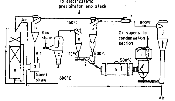
Fig. 5. Principal scheme of retort with solid
heat exchanger: a) waste-heat boiler, b) ash separator, c) dryer, d) ash heat exchanger,
e) dry oil shale separator, f) heat carrier separator, g) mixer, h) rotary drum reactor,
i) dust removal chamber, j) air-blown burner, k) heat carrier divider.
Operational data [21]:
|
GGS |
SHC |
Feed shale throughput, t/day |
182 |
463 |
850-950 |
795 |
|
226 |
485 |
|
Temperature after condensation, °C |
44 |
25 |
Yield of products:
GGS |
SHC |
|
Plant yield ( raw shale basis), % |
16.4 |
13.6 |
Yield of Fischer Assay oil, % |
78.3 |
77.3 |
Specific gas yield, m3/t |
507 |
40 |
C5 hydrocarbons in product gas, g/m3 |
24 |
376 |
The grade of retort feedstock has a strong influence on the economics of the retorting process. Moisture has favorable effect on the retorting process enabling accelerated evacuation of volatiles from pores of lump shale and increasing therefore the content of phenols in the oil. The physical and chemical properties of kukersite oil are greatly influenced by the presence of phenols.
Vertical retorts are only units now in constant operation in Estonia for retorting large particle kukersite on commercial basis.
The total amount of oil shale processed on two different types of retort plants (year 1993):
Solid heat carrier retort SHC 500 000 tons
Total 2 493 000 tons
Shale oil produced in year 1993:
Solid heat carrier retort SHC 65 000 tons
Total 366 000 tons
It gives the mean yield of crude oil 147 kg per ton of raw shale.
Present days the oil production is decreasing (latest years production of “Kiviter” [22] in tons):
|
1997 |
1998 |
Processed shale |
2 079 800 |
1 356 400 |
Oil |
375 200 |
128 900 |
Coke |
41 900 |
27 300 |
“Kiviter” was privatized in the end of 1997. From February 1999 after “Kiviter” bankruptcy there is a new factory for oil shale processing – Viru Keemia Group.
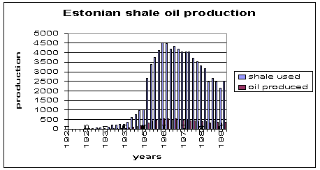
Fig.6. Production of shale oil in Estonia over the years.
5. Shale oil and
shale gas
Upon pyrolysis, kerogen is broken up into various organic fragments, much of it forming a viscous, oily liquid – shale oil.
One of the characteristics of kukersite causing considerable difficulties in its commercial scale processing is its bituminization on slow heating – the transition to the plastic state within the temperature range 350-400 °C. The maximum yield of thermobitumen is produced at 390-395 °C and it makes up to 55-57 % of organic matter. At these temperatures carbon content of solid residue (remaining after extraction with mixture of ethanol-benzene) is of the minimum value. However, as the heating continues to 510-520 °C the carbon content of the residue increases 2-3 fold. As a result most of the carbonaceous residue in semicoke is of secondary origin formed at the pyrolysis of unstable components like oxygen-containing compounds [23].
It has been established from laboratory Fischer retort studies that perceivable secondary cracking of the primary shale oil takes place on the final stages of kukersite shale semicoking it accelerating at temperatures above 430 °C. From this it is inexpedient to process kukersite at temperatures above 460-470 °C as the oil yield does not increase at higher temperatures noteworthy, its quality as well as that of gaseous products does not improve though energy requirements for heating the shale grows substantially [24].
Another characteristic feature of kukersite is the predominance of calcium carbonate in its mineral part. This compound dissociates at high temperatures forming free calcium oxide, which absorbs phenols on contact with the volatile products. The decomposition of carbonate minerals is endothermic and occurs at 600-750 °C for dolomite, and 600-900 °C for calcite. Carbon dioxide, a product of decomposition, dilutes the off-gases produced from retorting processes at the above decomposition temperatures.
Properties of oil produced by semicoking oil shale 21:
GGS |
SHC |
|
Density at 20 °C, g/cm3 |
0.9998 |
0.9685 |
18.7 |
3.5 |
|
Flash point, °C |
104 |
2.8 |
Initial boiling point, °C |
170 |
80 |
Calorific value, MJ/kg |
39.4 |
40.4 |
Phenolic compounds, % |
28.1 |
11.5 |
Fraction boiling up to 200 °C, % |
3.9 |
15.7 |
Fraction boiling at 200-350 °C |
28.3 |
33.7 |
Molecular mass, M |
287 |
275 |
Distillation, vol.% at 100 °C |
|
3 |
120 °C |
|
5 |
140 |
|
6 |
160 |
|
12 |
180 |
1 |
16 |
200 |
2 |
20 |
220 |
4 |
24 |
240 |
6 |
29 |
260 |
8 |
33 |
280 |
12 |
37 |
300 |
19 |
43 |
320 |
24 |
51 |
340 |
35 |
61 |
360 |
60 |
82 |
Elemental composition, % C |
83.5 |
83.0 |
H |
10.1 |
10.1 |
S |
0.7 |
0.8 |
O+N (dif) |
5.7 |
6.1 |
Volatile products (oxygen compounds) are thermally unstable. Therefore in order to obtain the maximum yield of oil with an elevated content of phenols including water soluble alkyl resorcinols it is utmost importance to evacuate the volatile products of kukersite retorting from reaction zone, particularly from micro-porous structure of shale lumps without delay. The best way to obtain this is processing kukersite in a flow of gaseous heat carrier with a low partial pressure of oil vapors.
Estonian kukersite shale oil distillates have a lower pour point, very low vanadium content, good pumpability and a moderate sulfur content. Shale oils are for the most part made up of oxygen compounds (ketones, ethers, hydroxybenzene and resorcinol series phenols). Due to this specific composition oil exhibit viscosity properties as a “polymer”.
The chemical group
composition of oil of Fisher retorting [25], wt.%:
Hydrocarbons |
|
Aliphatic and naphthenic |
15.8 |
Aromatic |
26.5 |
Heteroatomic: Neutral and basic |
45.4 |
Acidic (phenolic) |
12.3 |
Raw shale oil is nearly always contaminated to some extent by fine particles of shale that have been carried over from the retort. Sometimes the removal of fine particles is essential prior to most upgrading activities. This deashed, desalted and discharged from a circulating gasoline fraction shale oil is sent to distillation unit. The unit produces ordinarily three distillates: light “diesel oil” fraction (180-230 °C), light gas oil fraction (230-320 °C) and heavy gas oil fraction (320-360 °C). By blending these fractions commercial shale oil originated fuel oils are produced. Distillation residue is usually a coking feedstock.
The physical parameters of shale oil fractions [26] :
Fraction |
Density at 20 °C, kg/m3 |
Kinematic viscosity |
995 |
425 |
|
Light ”diesel oil” |
845 |
1.75 |
Light gas oil |
965 |
48 |
Heavy gas oil |
1028 |
4600 |
Chemical group composition of light and middle fractions of shale oil 21:
|
GGS |
SHC |
Fraction boiling up to 230 °C |
|
|
Alkanes and cycloalkanes |
14 |
15 |
Alkenes |
41 |
52 |
Aromatic hydrocarbons |
22 |
21 |
Neutral oxygen compounds |
16 |
11 |
Phenols |
7 |
1 |
Fraction yield, % |
3.9 |
15.7 |
Fraction boiling at 230-350 °C |
|
|
Alkanes and cycloalkanes |
8 |
6 |
Alkenes |
13 |
12 |
Aromatic hydrocarbons |
30 |
35 |
Neutral oxygen compounds |
22 |
27 |
Phenols |
27 |
20 |
Fraction yield, % |
28.3 |
39.3 |
Different fractions of shale oil are compatible amongst themselves; blends whatever ratios are stable in a wide temperature range. Fuel oil blends that are produced by blending shale distillate oils and heavy petroleum originated residues, as a rule, are also stable at every ratio [27].
The early post WWII development was characterized by introduction of synthetic domestic gas production, and this was the first time in worldwide practice. This process utilized high temperature gasification of oil shale in chamber ovens of special design. Since the 1970’s the production of gas was gradually reduced, and in 1987 the operation of chamber ovens was completely stopped.
Natural co-product in retorting is non-condensable shale gas, and this gas is used for heating of retorts.
Characteristics of retort gas, content of components in vol.% 21 :
|
GGS |
SHC |
CO2 |
21.8 |
1.7 |
H2S |
0.6 |
Traces |
CnHm |
1.0 |
26.3 |
C2H4 |
0.6 |
12.0 |
C3H6 |
0.3 |
8.9 |
C4H8 |
0.1 |
5.4 |
O2 |
0.6 |
0.8 |
CO |
3.9 |
8.6 |
H2 |
5.5 |
14.5 |
CnH2n+2 |
2.8 |
24.1 |
CH4 |
1.4 |
14.4 |
C2H6 |
0.9 |
6.3 |
C3H8 |
0.3 |
2.2 |
C4H10 |
0.2 |
1.2 |
N2 |
63.8 |
24.0 |
H2S (g/m3) |
8 |
Traces |
Calorific value (without > C5 hydrocarbons), MJ/m3 |
|
There is often gas clean-up system for retort off-gas, mainly compression and oil mist removal followed by ammonia recovery and desulfurization.
Properties of > C5 light gasoline recovered from gas 21:
|
GGS |
SHC |
Density at 20 °C, g/cm3 |
0.724 |
0.677 |
Refraction index, nD20 |
1.398 |
|
Molecular mass |
89 |
|
Initial boiling point, °C |
36 |
25 |
Alkanes, wt.% |
31.5 |
21.7 |
Alkenes, wt.% |
55.2 |
72.0 |
Aromatics, wt.% |
9.2 |
4.1 |
6. Other
recovery methods
Other recovery methods include any method for oil recovery from shale than retorting.
Extracting raw shales with various solvents can reveal differences in kerogen structure among the shales. Characteristic to Estonian shale is that solvents are unable to extract any significant portion of Estonian shale.
Organic extraction of raw shale 18:
Solvent |
|
Acetone |
1.14 |
Acetonitrile |
1.73 |
Benzene |
2.44 |
Carbon disulfide |
9.83 |
Carbon tetrachloride |
8.27 |
Chloroform |
2.62 |
Cyclohexane |
2.12 |
Dimethoxymethane |
17.72 |
Ethyl acetate |
2.91 |
Ethyl alcohol |
1.14 |
Hexane |
0.17 |
Methanol |
2.94 |
Methylene chloride |
1.74 |
Tetrahydrofuran |
37.78 |
Toluene |
3.14 |
Supercritical fluid extraction (SFE) with its advantages of sample preparation speed, high efficiency, greater suitability of off-line extracts for analysis, has been used for Estonian oil shale also, but only on analytical scale. The yields of Soxhlet extraction with chloroform and carbon dioxide SFE extracts at low temperature are very similar. Compounds, which are usually extracted from kukersite separately with chloroform and, after treatment with hydrochloric acid, with a benzene/methanol mixture, are co-extracted by the carbon dioxide modified with methanol [28].
There are studies about the treatment with supercritical CO2 at high temperature (350 °C), and these showed the liquefaction the organic part almost completely [29].
The presence of organic solvents (benzene, toluene, alcohols) accelerates bituminization process occurring at temperatures lower than those of active organic matter decomposition (340-360 °C). With mixture of solvent and water the yields up to 45 wt.% of organics were estimated [30]. At higher temperatures (370 °C) up 80 % of organic matter was liquefied.
Also the method of destructive hydrogenation using water and sodium formiate as hydrogen donors was used for destruction of kukersite [31]. At lower temperatures than that used in industrial processes (340-400 °C, working pressure up to 25 MPa) the yield of oil was the same level as by semicoking 65.5 %. On conversion in aqueous suspension, however, ketones are formed instead of alkyl resorcinols.
Technologies like solvent extraction are still in very early research mode and require considerable work to demonstrate their viability for large-scale operations.
One possible method to prevent air pollution with SO2 from fossil fuel is pretreatment of shale with sulfur oxidizing bacteria - bioleaching [32]. Biological desulfurization can eliminate pyrite without destruction of the matrix and the biological process also decreases the amount of ash. Pretreatment of Estonian oil shale by thermophilic Sulfolobus acidocaldarius and mesophilic Thiobacillus ferrooxidans in order to remove inorganic sulfur compounds (pyrite) has been studied. The bioreactor experiments demonstrated that the oxidation of pyrite by S.acidocaldarius is especially fast (96 % in four days). Bioleaching of oil shale by acidophilic bacteria is possible, but before evaluation the economic feasibility of the process, the reduction of the high acid consumption of this oil shale is needed. Therefore biological desulfurization of Estonian oil shale without any treatment cannot be used in practice [33]
7. Shale oil
upgrading
Catalytic processes which consume hydrogen are used to saturate olefines, to eliminate heterocyclic compounds (containing atoms of O, N, S), and stabilize oils to reduce tendency for oxidation and gum formation as a result of exposure to air and temperatures. Schemes know in petro-chemistry to get motor fuels of high quality from crude oil could not be used in case of shale oils due to the wide boiling range of heterocompounds present not only in heavy fractions but also in lighter ones.
Before II World War an industrial process for shale oil upgrading was worked out – retorting of oil shale was conjunct with cracking of shale oil in vapor phase [34]. Octane number of kukersite-derived cracking gasoline was 68. But it was established that cracking of shale oil in presence of lime (as well as shale ash containing lime and alumosilicates) results in increase of the yield of gasoline whereas a lot of phenolic oxygen is bound into carbonic acid and so great deal of hydrogen is released to form gasoline. Also resin donors are stabilized and H2S is formed at 400-500 °C.
Studies on upgrading shale oil were practically ceased by the end of fifties and the production of gasoline was stopped. New wave of studies on kukersite cracking and hydrogenation in laboratory scale were preformed in the beginning of eighties in Institute of Chemistry [35], [36]. In these studies it was found that sulfur present in oil shale is mainly tiophenic, and will be removed by 60-70 % on catalytical hydrogenation. Also several multistage upgrading schemes for industry were proposed but these did not found practical use.
There are some studies made about upgrading Estonian shale oil using Co-Mo catalyst at temperature 370 °C where a significantly higher content of non-aromatic hydrocarbons and a lower content of heteroatomic compounds were detected [37]. As a result of moderate hydrogenation, the chemical composition of shale oil became closer to that of natural crude oil. This makes upgrading of shale oil just into diesel fuel preferable.
8. Retorted
shale
Retorted shale is the major product of an oil shale operation. The physical and chemical properties of the spent shale are dependent both on the feed and retorting conditions. Mainly spent shale is charcoal-colored non-decarbonized solid containing around 5-10 % residual organic carbon.
Semicoke from Fischer Assay retorting, content on dry basis, %:
Carbon dioxide |
28.1 |
Ash |
64.8 |
Carbon |
7.6 |
Total sulfur |
1.5 |
Changes in mineral content, and the disappearance of minerals during processing can take place through various reaction pathways, which are determined by process variables such as temperature, time at maximum temperature, heating rate (kinetics of solid state reactions), and retort atmosphere. Higher temperatures at retorting generate higher decarbonation of minerals. The basicity of the spent shale is proportional to the degree of decarbonation, as is the leachability of alkali and alkaline-earth ions.
9. Shale oil
waters
Dissolved organics arise largely from the organic compounds in shale oil and will be present in the retort condense water. There is a dephenolization plant at “Kiviter” which serves to remove the mixed phenols from water stream. After the phenols are removed, the water is sent to the “Kiviter” wastewater plant for biological treatment before being discharged into surface water [38]
Water-soluble phenols accumulate in water layers of the retorting-unit condensation systems and additional quantities are obtained by washing the shale oil fractions with water. These phenol waters are subjected to dephenolization using a mixed extractant, particularly a mixture of butyl acetate and isopropyl ether. According to literature data the water-soluble alkyl phenols constitute up to 2 % of oil formed during oil shale retorting. (1/3 dissolved in the tar-water, 2/3 by supplementary washing of shale oil).
As is known from industrial practice of shale oil purification and phenolic water dephenolization, up to 8 kg of commercial water-soluble phenols (alkyl resorcinols) could be produced from one ton of shale oil.
Raw phenols of tar water represent a complex mixture (about 40 compounds) [39]:
alkyl derivatives oxybenzene (8-12 %)
resorcinol (88-92%).
The main method for obtaining alkyl resorcinol feed is the rectification of raw phenols in film type rectifier.
The content of main alkyl resorcinols in total water-soluble phenols:
Phenol |
Content, % |
5-methyl resorcinol (5-MR) |
27 |
5-ethyl resorcinol (5-ER) |
15 |
2,5-dimethyl resorcinol (2,5-DMR) |
8 |
4,5-dimethyl resorcinol (4,5-DMR) |
8,5 |
The shale oil phenols were used as feedstock for epoxy and other adhesive resins and glueing compounds, synthetic tanning agents, etc.
10. Combustion
of oil shale
For a long time, oil shale has been combusted directly in power stations in Estonia. Two big power stations near Narva (the Estonian Power Plant (EPP) – 1170 MW in 1995, and the Baltic Power Plant (BPP) – 1390MW) and two small ones in Kohtla-Järve (39 MW) and Ahtme (20 MW) burn pulverized oil shale with calorific value about 8-10 MJ/kg.
In EPP, fifteen (out of sixteen) boilers were in use. Usually, two boilers form one electricity production bloc. The pulverized fuel boilers consist of eight front wall burners, designed especially for oil shale combustion, on two levels. The air ratio in the burners is 1.25-1.35. Each boiler is supplied with fuel from four mills. The maximum fuel input is 122 t/h for each boiler. The steam production capacity of each boiler was 320 t/h (540 °C, 140 bar), in practice, production rates from 130 to 280 t/h have been used 42.
BPP has seventeen small tangentially fired boilers with steam production capacity of 190 t/h (520 °C and 100 bar), and eight big front wall fired boilers with steam production capacity 260 t/h (510 °C and 130 bar) 10.
Direct combustion of pulverized oil shale involves a number of problems resulting from its high ash content, like corrosion and fouling of the heat-transfer surfaces.
11. Spent oil
shale deposits
Spent-shale disposal is a major concern in oil shale industry because of the volume of the material to be disposed and the potentially harmful materials it contains. Landfill areas are the main place for retorted shale. The retorted shale occupies a volume 20-30 % greater then the raw in-place shale. Leachates of spent shale from retorting are rich in phenolic compounds, and contain these more than does raw shale leachate. Most compounds are present at the 10 to 50-ppb level, the exceptions being phenol, 5-methylresorcinol, and resorcinol, which are present in the 500- to 1000-ppb range. These waters are characterized by very few nitrogen- or sulfur-containing organic compounds. Also the carboxylic acids and aliphatic hydrocarbons are of low concentration in the spent shale leachates 18.
The second form of the spent shale is ash or burnt shale from shale fired power plants. Around 5 million tonnes of this residue are produced per annum. An environmentally valuable characteristic of oil shale is the high concentration of sulfur capturing components in the oil shale ash, which reduce the formation of sulfur dioxide emissions.
Bottom ash and fly ash collected by cyclones and field electrostatic precipitators goes mainly to the deposit. Only a small part of recovered fractions of ashes are used at present, but different fractions can be used in different applications.
Properties of different fractions of burnt shale [40]:
Property |
Fine fraction |
Finest fraction |
Specific surface area (m3/kg) |
50-120 |
320-500 |
Particle size (mm) |
10-30 |
|
CaO |
46-58 % |
28-35 % |
SiO2 |
20-28 % |
30-35 % |
Al2O3 |
6-8 % |
10-12 % |
K2O |
1-2 % |
4-6 % |
Special attention must be paid to fine fractions of fly ash, which remains in flue gases. Flue gases of power plants are discharged into the atmosphere through high chimneystacks. Because of low efficiency of particle removal by old electrostatic prepicitators (94-97 %), particle concentration remains as high as some grams per cubic meter, and they are responsible for the long-distance transport of air contaminants. The particles contain significant amounts of harmful trace metals and the emission norm stated in European Union directive on incineration of hazardous waste concerning the sum of Sb, As, Pb, Cr, Cu, Mn, Ni, V, Sn has been exceeded manifold [42].